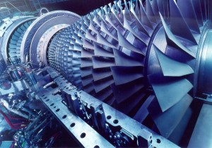
1. GENERAL
The laws of physics and fundamentals
pertaining to the theory of jet propulsion. The gas turbine engines used
to power Army aircraft are turboshaft powerplants. The energy produced
drives the power shaft. Energy is generated by burning the fuel-air
mixture in the engine and accelerating the gas tremendously. These
high-velocity gases are directed through turbine wheels which convert
the axial movement of the gas to a rotary motion. This rotary power is
used to drive a powershaft, which drives a propeller or a rotor
transmission.
2. LAWS OF MOTION
The theory of gas turbine engines is based on the laws and principles of physics discussed in the subparagraphs that follow.
Newton‘s First Law of Motion.
The first law states that a body in a state of rest remains at rest,
and a body in motion tends to remain in motion at a constant speed and
in a straight line, unless acted upon by some external force.
Newton‘s Second Law of Motion.
The second law states that an imbalance of forces on a body produces or
tends to produce an acceleration in the direction of the greater force,
and the acceleration is directly proportional to the force and
inversely proportional to the mass of the body.
Newton‘s Third Law of Motion.
The third law states that for every action there is an equal and
opposite reaction, and the two are directed along the same straight
line.
Bernoulli’s Principle.
This principle states that if the velocity of a gas or liquid is
increased its pressure will decrease. The opposite is also true. If the
velocity of a gas or liquid is decreased its pressure will increase.
This fact relates directly to the law of conservation of energy.
Einstein’s Law of Conservation of Energy.
This law states that the amount of energy in the universe remains
constant. It is not possible to create or destroy energy; however, it
may be transformed.
Boyle’s Law.
This law states that if the temperature of a confined gas is not
changed, the pressure will increase in direct relationship to a decrease
in volume. The opposite is also true — the pressure will decrease as
the volume is increased. A simple demonstration of how this works may be
made with a toy balloon. If you squeeze the balloon, its volume is
reduced, and the pressure of air inside the balloon is increased. If you
squeeze hard enough, the pressure will burst the balloon.
Charles’ Law.
This law states that if a gas under constant pressure is so confined
that it may expand, an increase in the temperature will cause an
increase in volume. If you hold the inflated balloon over a stove, the
increase in temperature will cause the air to expand and, if the heat is
sufficiently great, the balloon will burst. Thus, the heat of
combustion expands the air available within the combustion chamber of a
gas turbine engine.
Pressure and Velocity.
Air is normally thought of in relation to its temperature, pressure,
and volume. Within a gas turbine engine the air is put into motion so
now another factor must be considered, velocity. Consider a constant
airflow through a duct. As long as the duct cross-sectional area remains
unchanged, air will continue to flow at the same rate (disregard
frictional loss). If the cross-sectional area of the duct should become
smaller (convergent area), the airflow must increase velocity if it is
to continue to flow the same number of pounds per second of airflow
(Bernoulli’s Principle). In order to obtain the necessary velocity
energy to accomplish this, the air must give up some pressure and
temperature energy (law of conservation of energy). The net result of
flow through this restriction would be a decrease in pressure and
temperature and an increase in velocity. The opposite would be true if
air were to flow from a smaller into a larger duct (divergent area);
velocity would then decrease, and pressure and temperature would
increase. The throat of an automobile carburetor is a good example of
the effect of airflow through a restriction (venturi); even on the
hottest day the center portion of the carburetor feels cool. Convergent
and divergent areas are used throughout a gas turbine engine to control
pressure and velocity of the air-gas stream as it flows through the
engine.
3. THEORY OF JET PROPULSION
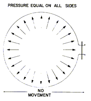
The principle of jet propulsion can be
illustrated by a toy balloon. When inflated and the stem is sealed, the
pressure is exerted equally on all internal surfaces. Since the force of
this internal pressure is balanced there will be no tendency for the
balloon to move.
If the stem is released the balloon will
move in a direction away from the escaping jet of air. Although the
flight of the balloon may appear erratic, it is at all times moving in a
direction away from the open stem.
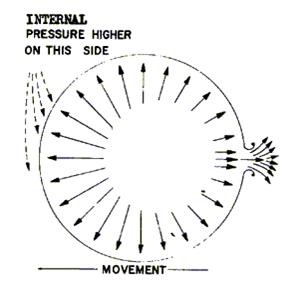
The balloon moves because of an
unbalanced condition existing within it. The jet of air does not have to
push against the outside atmosphere; it would function better in a
vacuum. When the stem area of the balloon is released, a convergent
nozzle is created. As the air flows through this area, velocity is increased accompanied by a decrease in air pressure.
In addition, an area of skin against which the internal forces had been
pushing is removed. On the opposite internal surface of the balloon, an
equal area of skin still remains. The higher internal pressure acting
on this area moves the balloon in a direction away from the open stem.
The flight of the balloon will be of short duration, though, because the
air in the balloon is soon gone. If a source of pressurized air were
provided, it would be possible to sustain flight of the balloon.
4. THEORY OF GAS TURBINE ENGINES
If the balloon were converted into a
length of pipe, and at the forward end an air compressor designed with
blades somewhat like a fan were installed, this could provide a means to
replenish the air supply within the balloon.
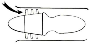 A
source of power is now required to turn the compressor. To extend the
volume of air, fuel and ignition are introduced and combustion takes
place. This greatly expands the volume of gas available.
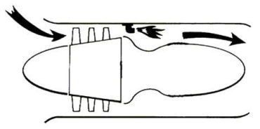
In the path of the now rapidly expanding
gases, another fan or turbine can be placed. As the gases pass through
the blades of the turbine, they cause it to rotate at high speed. By
connecting the turbine to the compressor, we have a mechanical means to
rotate the compressor to replenish the air supply. The gases still
possessing energy are discharged to the atmosphere through a nozzle that
accelerates the gas stream. The reaction is thrust or movement of the
tube away from the escaping gas stream. We now have a simple turbojet
engine.
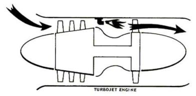
The turbojet engine is a high-speed,
high-altitude powerplant. The Army, at present, has no requirement for
this type of engine. Because it is simple and easy to operate and
maintain, however, the Army does use the gas turbine engine. The simple
turbojet engine has primarily one rotating unit, the compressor/turbine
assembly. The turbine extracts from the gas stream the energy necessary
to rotate the compressor. This furnishes the pressurized air to maintain
the engine cycle. Burning the fuel-air mixture provides the stream of
hot expanding gas from which approximately 60 percent of the energy is
extracted to maintain the engine cycle. Of the total energy development,
approximately 40 percent is available to develop useful thrust
directly.
If we had ten automobile engines that
would equal the total shaft horsepower of a turbine engine, it would
take six of these engines to turn the compressor, and the other four
would supply the power to propel the aircraft. The amount of energy
required to rotate the compressor may at first seem too large; however,
it should be remembered that the compressor is accelerating a heavy mass
(weight) of air towards the rear of the engine. In order to produce the
gas stream, it was necessary to deliver compressed air by a mechanical
means to a burner zone. The compressor, being the first rotating unit,
is referred to as the N1 system.
With a requirement for an engine that
delivers rotational shaft power, the next step is to harness the
remaining gas stream energy with another turbine (free turbine). By
connecting the turbine to a shaft, rotational power can be delivered to
drive an aircraft propeller, a helicopter rotor system, a generator, a
tank, an air cushion vehicle (ACV), or whatever is needed. The power
shaft can extend from the front, back, or from an external gearbox. All
of these locations are in use on various types of Army engines at
present.
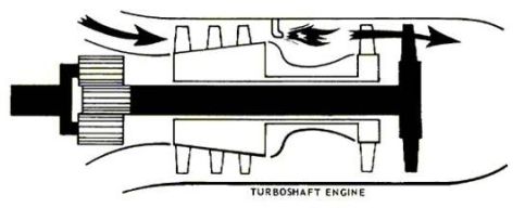
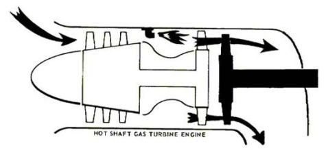
The following sketch shows a turboshaft
engine with the power shaft extended out the front. The bottom sketch
shows the same engine with the power shaft extending out the back.
The basic portion of the turbine engine,
the gas producer, extracts approximately 60 percent of the gas stream
energy (temperature/pressure) to sustain the engine cycle. To develop
rotational shaft power, the remaining gas stream energy must drive
another turbine. In Army engines today, a power turbine that is free and
independent of the gas producer system accomplishes this task. The
power turbine and shaft (N2 system) are not mechanically connected to
the gas producer (N1 system). It is a free turbine. The gas stream
passing across the turbines is the only link between these two systems.
The free-turbine engine can operate over wide power ranges with a
constant output-shaft speed.
In operation, the gas producer (N1)
system automatically varies its speed, thereby controlling the intensity
of the gas stream in relation to the load applied to the power (N2)
shaft. This is accomplished by a fuel metering system that senses engine
requirements. The free turbine design has revolutionized the methods of
application of shaft turbine engines. Why a shaft turbine? Why is a
perfectly good jet engine used to drive a propeller? Because in the
speed range that Army aircraft operate, the propeller or helicopter
rotor is more efficient. With a turbojet engine, power (thrust) produced
is roughly the difference between the velocity of the air entering the
engine and the velocity of the air exiting from the engine. Efficiency
of the engine (power producer versus fuel consumed) increases with speed
until it is 100 percent efficient when the forward speed of the engine
is equal to the rearward speed of the jet. It is this low efficiency at
takeoff and at low cruising speed (i.e., 400 mph) that makes the
turbojet engine unsuitable for use in Army aircraft. The propeller does
not lack efficiency at low speed; the reverse is true, in that
efficiency falls off at high speed. The result is to harness the jet
engine’s gas stream energy to drive a propeller or helicopter rotor
system, thereby taking advantage of the best features of both.
Aircraft reciprocating engines operate
on the four-stroke, five-event principle. Four strokes of the piston,
two up and two down, are required to provide one power impulse to the
crankshaft. Five events take place during these four strokes: the
intake, compression, ignition, power, and exhaust events. These events
must take place in the cylinder in the sequence given for the engine to
operate.
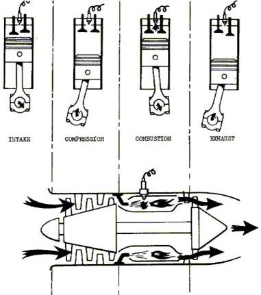
Although the gas turbine engine differs
radically in construction from the conventional four-stroke, five-event
cycle reciprocating engine, both involve the same basic principle of
operation. In the piston (reciprocating) engine, the functions of
intake, compression, ignition, combustion, and exhaust all take place in
the same cylinder and, therefore, each must completely occupy the
chamber during its respective part of the combustion cycle. In the gas
turbine engine, a separate section is devoted to each function, and all
functions are performed at the same time without interruption.
5. SUMMARY
The theory of gas turbine engine
operation is based on the laws or principles of physics. The principle
of jet propulsion can be illustrated by a toy balloon. When the balloon
is inflated and the stem is unsealed the balloon will move in a
direction away from the escaping jet of air. If the balloon is converted
into a length of pipe, and at the forward end an air compressor is
installed to supply air for combustion, and to expand the volume of air,
fuel and ignition are introduced and combustion takes place. Then, in
the path of the expanding gases a turbine rotor is installed. As the
gases pass through the turbine blades, the turbine rotor is rotated at
high speed. This turbine rotor is connected to the compressor shaft, and
we now have a means to rotate the compressor to replenish the air
supply. The remaining gases are discharged to the atmosphere. The
reaction of these gases is thrust, or movement of the tube away from the
escaping gases. This is a simple turbojet engine.
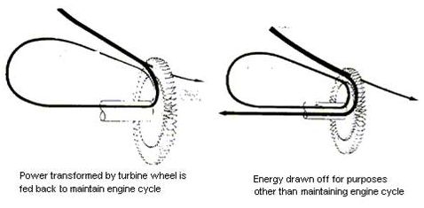
In the turbojet engine, approximately 60
percent of the energy is extracted to rotate the compressor, while the
remaining 40 percent is used to develop thrust. In the turboshaft
engine, the remaining energy is used to drive a turbine rotor attached
to a transmission or propeller. On a free-turbine engine, the gas stream
passing across the turbines is the only link between the two turbine
rotors. One turbine drives the compressor and the other turbine propels
the aircraft. The free-turbine engine is used in Army aircraft.
The gas turbine engine differs radically
in construction from the reciprocating engine in that the turbine
engine has a separate section for each function, while in the
reciprocating engine all functions are performed in the same cylinder.
Sumber : free-ed.net
Tidak ada komentar:
Posting Komentar